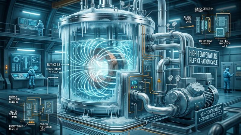
Cryogenics and Superconducting Magnet Technology: The World of Refrigeration Cycles Approaching Absolute Zero and High Magnetic Fields
In modern cutting-edge science and infrastructure, “Cryogenics” and “Superconductivity” have become indivisible core technologies. MRIs in medicine, giant particle accelerators driving high-energy physics, and the superconducting maglev train, a next-generation high-speed transport system. All of these are the crystallization of “cryogenics” to maintain the superconducting state of zero electrical resistance, and “superconducting magnet engineering” to stably generate and maintain powerful magnetic fields.
This article thoroughly elucidates the depths of cryogenics and superconducting magnet technology, from the thermodynamics of refrigeration cycles pushing to the absolute limit of zero (0 K = -273.15 ℃), to the microscopic physical properties of practical superconducting materials, coil designs capable of withstanding massive electromagnetic forces, and the physical mechanisms of protection systems that prevent “quenching”—a fatal destruction of the state.
Chapter 1: Thermodynamics of Cryogenics
The gateway to the world of cryogenics is opened by thermodynamic cycles that liquefy gases. Under atmospheric pressure, the boiling point of nitrogen is 77.3 K, hydrogen is 20.3 K, and helium (He-4) is 4.2 K. To generate these cryogenic refrigerants, or to cool systems without using refrigerants, humanity has constructed numerous exquisite refrigeration cycles.
Joule-Thomson Effect and Helium Liquefaction
The phenomenon where the temperature of a gas changes upon adiabatic expansion is called the Joule-Thomson effect. In an isenthalpic process where the enthalpy $h$ is constant, the Joule-Thomson coefficient $\mu_{JT}$, representing the rate of temperature $T$ change with respect to pressure $P$, is defined as follows:
$$ \mu_{JT} = \left( \frac{\partial T}{\partial P} \right)_h = \frac{1}{C_p} \left[ T \left( \frac{\partial v}{\partial T} \right)_P - v \right] $$Here, $C_p$ is the specific heat at constant pressure, and $v$ is the specific volume. Only in the region where $\mu_{JT} > 0$ (below the inversion temperature) does the temperature drop ($\Delta T < 0$) along with a pressure drop ($\Delta P < 0$). Because the inversion temperature of helium is exceedingly low at about 40 K, simply expanding it from room temperature will cause it to heat up. Therefore, to liquefy helium, the Claude cycle is used. It involves first precooling the helium using liquid nitrogen or similar, or performing isentropic expansion (adiabatic expansion extracting external work) using a turbo-expander to cool it below the inversion temperature, followed by isenthalpic expansion through a J-T valve in the final liquefaction stage. On a T-s (temperature-entropy) diagram, this process is depicted as a combination of an isentropic vertical drop in the turbine from the high-pressure line and a drop along an isenthalpic curve at the J-T valve, plunging into the gas-liquid coexistence region.
Gifford-McMahon (GM) Cryocoolers and Pulse Tube Cryocoolers
Closed-cycle GM (Gifford-McMahon) cryocoolers are frequently used in MRIs and research cryostats. A GM cryocooler realizes Simon expansion (a cycle of isothermal compression and adiabatic expansion) by switching the supply and exhaust of high-pressure helium gas from a compressor via a rotary valve and reciprocating a displacer (a piston containing regenerator material) within a cylinder. While similar to the reverse Stirling cycle, by controlling the phase difference between the valve and the piston, it delivers a large cooling capacity at a lower frequency.
The temperature dependence of heat capacity plays a decisive role for the regenerator. At cryogenic temperatures (below 10 K), the lattice specific heat of solids drops precipitously according to Debye’s $T^3$ law, and ordinary metals (like copper or lead) can no longer store heat. Thus, for the second-stage regenerator of 4 K class GM cryocoolers, magnetic regenerator materials (such as $Er_3Ni$ or $HoCu_2$) that utilize the giant magnetic specific heat associated with magnetic phase transitions are employed, enabling the direct generation of 4.2 K (cryogen-free operation).
Furthermore, the Pulse Tube Cryocooler drastically improved reliability by eliminating moving parts. Instead of a displacer, it uses a phase shifter (an orifice and buffer tank) to acoustically optimize the phase difference between the sound wave (pressure wave) and the gas displacement, pumping heat to the high-temperature end without any moving components.
The Path to the Millikelvin Regime: Dilution Refrigeration and Adiabatic Demagnetization
By depressurizing and boiling 4.2 K liquid helium, one can descend along the vapor pressure curve to reach about 1 K. However, to approach absolute zero into the millikelvin (mK) regime, a “Dilution Refrigerator” is required, which utilizes the phase separation phenomenon of an isotopic mixture of helium-3 (He-3) and helium-4 (He-4). Below 0.87 K, the $He^3-He^4$ liquid mixture separates into two phases: a $He^3$-rich phase (close to pure $He^3$) and a $He^3$-dilute phase (a phase where about 6.6% $He^3$ is dissolved in superfluid $He^4$). When $He^3$ atoms “evaporate” (dissolve) from the rich phase into the dilute phase, an endothermic phenomenon occurs due to the enthalpy difference. By continuously circulating this process, cryogenic temperatures from tens of mK down to less than 10 mK are stably maintained.
Additionally, by using Adiabatic Demagnetization technology, which exploits the entropy of magnetic dipoles, it is possible to reach the world of microkelvins ($\mu K$).
Chapter 2: Physical Properties and Manufacturing Technologies of Practical Superconducting Materials
To generate strong magnetic fields, the conductors forming the windings must maintain their superconducting state under high magnetic fields and be capable of carrying massive currents (critical current). The superconducting state is maintained only within a three-dimensional critical surface bounded by three critical values: temperature $T$, magnetic field $H$, and current density $J$ ($T_c, H_c, J_c$).
Type-II Superconductors and the Pinning Effect
All materials used in high-field magnets are Type-II Superconductors. When the lower critical magnetic field $H_{c1}$ is exceeded, magnetic flux enters the interior of the superconductor as quantized “flux quanta” ($\Phi_0 = h/2e \approx 2.07 \times 10^{-15} \text{ Wb}$) (mixed state). The superconducting state is macroscopically maintained until the external magnetic field reaches the upper critical magnetic field $H_{c2}$. However, if a magnetic flux $\vec{B}$ is present while a current $\vec{J}$ is flowing, a Lorentz force ($\vec{F}_L = \vec{J} \times \vec{B}$) acts on the flux quanta. If the magnetic flux moves (flux flow), a voltage is generated by electromagnetic induction, Joule heat is produced, and superconductivity is destroyed. To prevent this, it is essential to introduce artificial defects (normal-conducting precipitates, grain boundaries, dislocations, etc.) into the material to capture the magnetic flux at those locations, known as “Flux Pinning”. The condition under which the pinning force $\vec{F}_p$ overcomes the Lorentz force ($\vec{F}_L \le \vec{F}_p$) determines the macroscopic critical current density $J_c$ of the material.
NbTi (Niobium-Titanium) Multifilamentary Wires and Copper Matrix
The most widely used material in MRIs and accelerators is the NbTi alloy ($T_c \approx 9.2 \text{ K}, H_{c2} \approx 11 \text{ T}$ at 4.2 K). NbTi is highly ductile and easy to plastically work. Practical wires are not solid monofilaments but possess an “ultra-fine multifilamentary structure” where tens of thousands of micron-order NbTi filaments are embedded in a high-purity oxygen-free copper (OFC) matrix. This is to prevent “magnetic instability (flux jump)”. When magnetic flux abruptly enters a superconductor, it generates heat, the temperature rise lowers the critical current, which invites further magnetic flux penetration, leading to thermal runaway (quench). To satisfy stability criteria (adiabatic and dynamic stability criteria) that prevent this, the superconducting filaments must be thinned down to tens of $\mu m$ or less and encased in copper, which has excellent thermal and electrical conductivity.
Nb3Sn (Niobium-Tin) and Heat Treatment Technology for Brittle Compounds
For strong magnetic fields exceeding 10 T (NMR, ITER, high-field research), Nb3Sn ($T_c \approx 18.3 \text{ K}, H_{c2} \approx 23 \text{ T}$ at 4.2 K), an A15-type intermetallic compound, is used. However, Nb3Sn is extremely brittle and cannot be bent as is (strain severely degrades its critical properties). Therefore, ingenious manufacturing techniques such as the “Bronze Route” and “Internal Tin Process” have been developed. When winding the coil, it is processed and wound using unreacted Nb (niobium) filaments and a matrix (such as bronze) containing Sn (tin) (Wind & React method). After being formed into a coil shape, it is subjected to heat treatment at 600–700 ℃ for tens of hours. Through a solid-state diffusion reaction, Nb and Sn combine to form a Nb3Sn layer in the filament sections.
The Rise of High-Temperature Superconducting Wires (REBCO / BSCCO)
Cuprate high-temperature superconductors (HTS), which exhibit superconductivity above the liquid nitrogen temperature (77 K), demonstrate astonishing magnetic field tolerance exceeding 100 T when used at cryogenic temperatures like $20 \text{ K}$ or $4.2 \text{ K}$. Particularly noteworthy are REBCO (Rare-Earth Barium Copper Oxide, $RE Ba_2 Cu_3 O_{7-\delta}$) thin-film wires. An intermediate buffer layer is highly oriented on a high-strength metal tape substrate like Hastelloy via the IBAD (Ion Beam Assisted Deposition) method, and a REBCO layer is epitaxially grown on top of it. A REBCO layer just 1–2 $\mu m$ thick can carry hundreds of amperes. With the advent of HTS, the feasibility of ultra-high magnetic field NMR exceeding 25 T and compact fusion reactors (like SPARC) is rapidly emerging.
Chapter 3: Superconducting Magnet Design and High Magnetic Field Engineering
The design of superconducting magnets is a trinity of engineering encompassing electromagnetism, cryogenic thermodynamics, and extreme solid mechanics.
Coil Geometry and Massive Electromagnetic Force (Lorentz Force)
The most basic solenoid coil generates a powerful magnetic field along its central axis. On the other hand, in dipole magnets used to bend beams in particle accelerators, uniform dipole magnetic fields are formed by combining special racetrack-type coils known as saddle-shaped, cosine-theta ($\cos \theta$) wound, or block-wound coils. The greatest barrier in magnet design is the massive electromagnetic force (Lorentz force $\vec{f} = \vec{J} \times \vec{B}$) acting on the superconducting wires themselves. For example, in large magnets with a central magnetic field exceeding 10 T, the hoop stress attempting to push the coil outward reaches hundreds of MPa (hundreds of atmospheres). To withstand this, the outer periphery of the coil is equipped with a shrink ring made of tough non-magnetic stainless steel or aluminum alloy, or a robust binding structure (mechanical reinforcement) using Carbon Fiber Reinforced Plastics (CFRP) or Glass Fiber Reinforced Plastics (GFRP). The windings are vacuum pressure impregnated (VPI) with epoxy resin, integrating them into a rigid body that does not forgive even minute frictional heating (dynamic displacement of wires).
Persistent Current Mode
An extremely important technology for MRI and NMR is the Persistent Current Mode. If the entire circuit of a superconducting magnet can be closed into a loop with superconductors, the resistance $R = 0$ means that even if the external power supply is disconnected, the current $I$ will theoretically never decay semi-permanently (time constant $\tau = L/R \to \infty$). This is realized by a “Persistent Current Switch (PCS)”. A PCS is a bypass circuit of superconducting wire connected in parallel with the magnet. The PCS is wound with a heater. By heating the heater to bring the PCS section into a normal conducting state (with resistance) above temperature $T_c$, it acts as a “switch OFF (open)”, and current is excited from the external power supply into the main magnet body (inductance $L$). Once the predetermined current value is reached, the heater is turned off to return the PCS to the superconducting state (switch ON, zero resistance). Thereafter, when the current from the external power supply is gradually lowered, the current begins to circulate within the closed loop of the zero-resistance PCS and the magnet, instead of the external circuit. This completes the persistent current mode. With this technology, the magnetic field is maintained with extremely high stability of 0.01 ppm/h or less over several years.
Chapter 4: Physics of the Quench Phenomenon and Protection Systems
The most formidable phenomenon in superconducting magnets is the “Quench”. A quench is a phenomenon in which a portion of the coil undergoes a temperature rise due to some thermal disturbance (frictional heat from minute wire movements, resin cracking, radiation incidence, etc.), exceeds $T_c$, and transitions into the normal conducting state (resistive state).
Physical Mechanism of Quenching and Rapid Propagation
When a normal conducting zone occurs, a large current flows through it, generating Joule heat ($I^2 R$). This heat is transmitted to the surrounding superconducting regions via thermal conduction, and the normal conducting zone expands three-dimensionally at an explosive speed. This is known as “Normal Zone Propagation”. If a quench occurs, the massive magnetic energy ($E = \frac{1}{2} L I^2$) stored inside the magnet attempts to be entirely consumed as Joule heat within the coil itself. For instance, a single dipole magnet in the LHC stores 7 MJ of energy, equivalent to several kilograms of TNT explosive. Left unchecked, the temperature of the localized “hot spot” that has become normal-conducting will exceed its melting temperature (1085 ℃ for copper), literally burning out and destroying the coil. Furthermore, if it is immersed in a liquid helium bath, the rapid heating will cause the liquid helium to explosively vaporize (expanding in volume by about 700 times), leading to a sudden pressure spike inside the cryostat.
Adiabatic Heat Equation and Dump Circuit Calculations
The fundamental thermodynamic model for protecting a coil from quenching is based on calculating the temperature rise using an adiabatic approximation. The temperature $T_m$ of the hot spot at time $t$ after the onset of the quench is described by the following adiabatic heat equation:
$$ \int_{0}^{\infty} I(t)^2 \, dt = S^2 \int_{T_{op}}^{T_{m}} \frac{\gamma C_p(T)}{\rho(T)} \, dT $$The left side is the time integral of the squared current, referred to by an index called “MIITs (Mega Amps Squared Seconds)” indicating the severity of the quench. The right side is the temperature integral of the intrinsic material properties (cross-sectional area $S$, density $\gamma$, specific heat $C_p$, electrical resistivity $\rho$). To keep the hot spot temperature $T_m$ within a safe range (e.g., below 150 K, a temperature that will not cause disconnection due to thermal strain), the left side $\int I^2 dt$ must be minimized.
Protection Systems: Energy Dump and Heater Triggers
A Quench Protection System (QPS) to prevent quench damage is indispensable.
- Quench Detectors: Using a bridge circuit that monitors the differential between the voltage across the ends of the coil and the center tap, it cancels the inductive voltage $L(di/dt)$ to rapidly detect minute voltages (tens of mV) generated by resistance.
- Energy Dump Resistor: The moment a quench is detected, an external circuit breaker is opened, and a massive normal-conducting “Dump Resistor ($R_d$)” connected in series with the coil is inserted into the circuit. This allows most of the magnetic energy to be consumed as heat in the dump resistor outside the cryostat. The current decay time constant becomes $\tau = L / (R_{coil} + R_d)$, allowing the current to rapidly attenuate.
- Quench Heaters: If the coil is extremely large, relying solely on a dump resistor would result in excessively high voltage ($V = I \times R_d$), posing a risk of dielectric breakdown (arc discharge). Thus, simultaneously with quench detection, a pulse current is passed through heaters affixed to the coil’s surface, forcibly heating the entire coil to intentionally cause the “entire region to quench”. This disperses the Joule heating across the whole coil, preventing a localized hot spot temperature rise.
Chapter 5: Giant Systems Supporting State-of-the-Art Infrastructure
Superconducting magnets have transcended the confines of laboratories, operating as massive infrastructures supporting modern society.
JR Central Linear Chuo Shinkansen (L0 Series Superconducting Magnets)
The Superconducting Maglev (SCMAGLEV), upon which Japan’s prestige rests, is equipped with NbTi superconducting magnets on the vehicles, generating powerful repulsive and attractive forces with propulsion and levitation coils on the ground to realize levitated travel at a speed of 500 km/h. Because vehicle magnets are exposed to harsh vibration environments, they employ a load-bearing structure with high mechanical rigidity while minimizing heat intrusion to the absolute limit. While early experimental vehicles used cooling systems with liquid helium and liquid nitrogen, for the latest L0 series, high-performance onboard closed-cycle GM-JT cryocoolers have been developed, envisaging operation that does not require external helium replenishment for long periods.
Proliferation of Medical MRI (3T to 7T)
The most numerous superconducting systems in operation worldwide are MRIs (Magnetic Resonance Imaging devices). To align the spins of hydrogen nuclei in the human body, they require a uniform, powerful magnetic field space (bore) of 1.5 T to 3.0 T, and up to 7.0 T for the latest research and clinical uses. MRI magnets are composed of solenoid coils made of NbTi wires and are stably driven by the persistent current mode. Thanks to advances in Zero-Boil-Off technology for helium evaporation, systems that do not require regular cryogen replenishment have become mainstream.
CERN Large Hadron Collider (LHC) and the ITER Fusion Reactor
At the LHC in Geneva, the pinnacle of high-energy physics, 1,232 superconducting dipole magnets are lined up in a 27 km circumference tunnel. To generate the 8.3 T magnetic field needed to bend the proton beams, the NbTi coils are cooled by 1.9 K Superfluid Helium (He-II). Superfluid helium has zero viscosity and thermal conductivity thousands of times greater than pure copper, so it functions as the “ultimate refrigerant,” permeating minute gaps inside the coils to remove heat extremely efficiently. Meanwhile, at the International Thermonuclear Experimental Reactor (ITER) under construction in southern France, giant toroidal field coils and a central solenoid coil for confining plasma are being built. The central solenoid reaches 13 m in height and weighs 1,000 tons, generating a 13 T fluctuating magnetic field; hence, an Nb3Sn conductor with a special structure called CICC (Cable-in-Conduit Conductor) is employed. This is the ultimate conductor that balances resistance to immense electromagnetic forces with high cooling performance by twisting hundreds of superconducting strands inside a stainless steel pipe and forcibly circulating Supercritical Helium through the gaps.
Chapter 6: The Frontier of Cryogenic Engineering
Technological innovation in cryogenics and superconductivity continues to accelerate even now.
Dilution Refrigerators for Quantum Computers
Currently, the development of quantum computers using superconducting qubits (such as Transmons) is a global competition. To protect the coherence of quantum states (superposition states) from thermal noise, the chips must be placed in a temperature environment at the absolute zero limit of 10–15 mK. Large-scale cryogen-free dilution refrigerators are used for this purpose. They cool from room temperature to 4 K using a pulse tube cryocooler, and from there drop down to millikelvins using a He-3/He-4 circulation cycle. The key to hardware design lies in multi-stage thermal shield designs that block heat inflow while bringing numerous coaxial cables into the cryogenic region.
Cryogen-Free Magnets and Conduction Cooling Technology
For many years, expensive and difficult-to-handle liquid helium was essential for the operation of superconducting magnets. However, with improvements in the performance of high-temperature superconducting wires and higher outputs of compact cryocoolers like GM cryocoolers, Conduction Cooled magnets—which use no liquid cryogen and directly connect the cryocooler’s cooling stage to the magnet via copper thermal links—are rapidly proliferating. This makes it possible to generate strong magnetic fields with a single touch of a button, explosively broadening the base of applications in materials science, condensed matter physics, and the medical field.
Integration with the Hydrogen Society: Liquid Hydrogen Infrastructure and MgB2
Liquid hydrogen (boiling point 20.3 K) is attracting attention as an energy carrier for a future carbon-neutral society. This 20 K temperature zone is cryogenic enough to operate the intermetallic compound superconductor Magnesium Diboride ($MgB_2$, $T_c \approx 39 \text{ K}$), discovered in Japan in 2001, as well as the aforementioned high-temperature superconductors (REBCO / BSCCO). A paradigm shift in cryogenic energy infrastructure has been proposed—“cooling superconducting power transmission cables and Superconducting Magnetic Energy Storage (SMES) devices using liquid hydrogen as a refrigerant, while simultaneously transporting and utilizing the hydrogen itself as fuel”—and demonstration experiments have already begun.
Appendix A: Detailed Analysis of Refrigeration Cycle Thermodynamics and T-s Diagrams
To gain a deeper understanding of the essence of cryogenic refrigeration cycles, we strictly trace the behavior of the Claude cycle for helium liquefaction on a T-s (temperature-entropy) diagram. Helium gas is isothermally compressed from a state of 1 atm (about 0.1 MPa) at room temperature (300 K) to about 2 MPa (20 atm) by a compressor. The heat of compression generated in this process is expelled to the outside by a water-cooled heat exchanger (on the T-s diagram, this is a process where entropy decreases along an isotherm). Subsequently, the high-pressure gas is sent to a multi-stage counter-flow heat exchanger. Here, it exchanges heat with low-temperature, low-pressure gas returning without liquefying, undergoing isobaric cooling (a process where temperature and entropy fall along an isobar on the T-s diagram). However, helium cannot be liquefied by the Joule-Thomson effect alone, so the bulk of the gas (about 60–80%) is diverted midway to a turbo-expander. Inside the turbine, the gas adiabatically expands while spinning an impeller to extract external work. Ideally, this process is an isentropic expansion (a vertical drop along an isentropic line), resulting in a sudden drop in temperature (for example, down to about 15 K). This low-pressure gas, cooled by the turbine, returns to the heat exchanger and serves to precool the remaining high-pressure gas that proceeded without being diverted. Through this precooling, the high-pressure gas is cooled to about 6 K, far below the inversion temperature of helium (about 40 K). Finally, this 6 K high-pressure gas passes through a Joule-Thomson valve (J-T valve). The expansion at the J-T valve is unaccompanied by external work, making it an isenthalpic expansion where enthalpy is conserved. On the T-s diagram, the state changes along an isenthalpic line (a curve descending to the right) and plunges into the coexistence region of liquid and gas phases (saturation dome). Consequently, a portion of the gas liquefies (temperature 4.2 K, pressure 1 atm) and is recovered as liquid helium. The unliquefied gas returns again to the heat exchanger to cool the system.
Appendix B: Cross-Sectional Structure of NbTi Superconducting Multifilamentary Wires and Dynamic Stability Criteria
As previously mentioned, practical superconducting wires adopt a multifilamentary structure in which a multitude of superconducting filaments are arranged within a copper matrix. We quantitatively explain the necessity of this structure from the perspective of magnetic instability (flux jump). When a magnetic field penetrates a superconductor, a shielding current (pinning current) flows. When the external magnetic field fluctuates, magnetic flux moves and generates Joule heat. If the heat capacity of the superconductor is small and its thermal conductivity is low, this heat generation causes a localized temperature rise, decreasing the critical current density $J_c$. The decrease in $J_c$ invites further magnetic flux penetration, triggering further heat generation. The phenomenon where this positive feedback loop leads to a catastrophic quench is the “flux jump”.
The first criterion to prevent this is the “Adiabatic stability criterion”. Assuming the filament radius is $d$, the specific heat is $C$, and the temperature derivative of the critical current density is $-(dJ_c/dT)$, the maximum dimension $d_{max}$ to prevent a flux jump is proportional to the following equation:
$$ d_{max} \propto \sqrt{ \frac{C}{\mu_0 J_c |dJ_c/dT|} } $$At cryogenic temperatures, the specific heat $C$ is extremely small, so $d_{max}$ is typically tens of $\mu m$ or less. Therefore, the superconductor must be divided into micron-order fine wires (filaments).
However, thinning them down is not enough. If many filaments are bundled, electromagnetic coupling (coupling currents) occurs between them, causing the whole entity to behave as a single thick superconductor. To prevent this, the filaments are encased in a normal conducting metal (like copper), and the entire wire is “twisted” longitudinally. By shortening the twist pitch $l_p$, the loop area of the coupling current is reduced, severing the magnetic coupling. Furthermore, to rapidly dissipate heat to the surroundings when a thermal disturbance occurs, and to bypass the current when it transitions to the normal conducting state, high-purity oxygen-free copper with high thermal and electrical conductivity (copper with a high RRR: Residual Resistivity Ratio) is used as the matrix. This is called the “Dynamic stability criterion”. The volume ratio of superconducting filaments to the copper matrix (Cu/SC ratio) is typically in the range of 1.0 to 10.0, meticulously designed according to the magnet’s application and stability requirements.
Appendix C: Dump Circuits During a Quench and Quantitative Design of Maximum Voltage
In magnet protection design, the selection of the dump resistor $R_d$ is a critically important process of finding a compromise between magnet safety and electrical insulation. When a magnet with inductance $L$ and initial operating current $I_0$ quenches, the current decay in a circuit with an inserted dump resistor $R_d$ follows this equation, taking into account the normal-conducting resistance of the coil itself $R_c(t)$:
$$ L \frac{dI}{dt} + (R_c(t) + R_d) I = 0 $$For simplicity, assuming $R_d$ is inserted immediately after the quench and $R_c(t)$ is sufficiently small compared to $R_d$, the current decays exponentially:
$$ I(t) = I_0 \exp\left(-\frac{R_d}{L} t\right) $$At this time, the MIITs integral is calculated as follows:
$$ \int_0^\infty I^2 dt = \int_0^\infty I_0^2 \exp\left(-\frac{2R_d}{L} t\right) dt = \frac{L I_0^2}{2 R_d} $$From the aforementioned adiabatic heat equation, to suppress the hot spot temperature below an allowable value (e.g., 150 K), this MIITs integral must be below a certain critical value $U_{max}$ (a constant determined by the conductor’s physical properties).
$$ \frac{L I_0^2}{2 R_d} \le U_{max} \implies R_d \ge \frac{L I_0^2}{2 U_{max}} $$In other words, from the viewpoint of thermal protection, the dump resistor $R_d$ must be sufficiently large.
On the other hand, at the moment the dump resistor is inserted, a high inductive voltage $V_{max}$ is generated across both ends of the magnet.
$$ V_{max} = I_0 R_d $$This voltage is applied between the coil and the ground, or between layers of the coil. Letting the maximum dielectric withstand voltage that the magnet’s insulating coating (Kapton or epoxy resin) can endure be $V_{ins}$:
$$ I_0 R_d \le V_{ins} \implies R_d \le \frac{V_{ins}}{I_0} $$In other words, from the viewpoint of electrical insulation, the dump resistor $R_d$ must be sufficiently small.
The dump resistor value, the magnet’s inductance (and thus the balance between the number of turns and current value), and the insulation structure are designed to satisfy these two conflicting conditions. In gigantic magnets (such as the LHC or ITER), because $L$ is extremely large, it becomes impossible to satisfy both conditions with a dump resistor alone. Therefore, a more advanced active protection system becomes essential, which uses the aforementioned “Quench Heaters” to forcefully and rapidly ramp up $R_c(t)$, gaining effective resistance while preventing localized heat concentration.
The fusion of these meticulous calculations and materials science approaches in cryogenic environments can truly be called an engineering miracle achieved by modern superconducting magnet technology.
Conclusion: Extreme Engineering Continuing to Challenge the Limits
Cryogenics, pushing the limits of physical laws at absolute zero, and superconducting magnet technology manipulating massive energy. These technologies are a rare bridge directly connecting microscopic physical phenomena like quantum mechanics to huge, meter-scale infrastructures like maglev trains and giant accelerators.
While side by side with the terror of thermal runaway from a quench, a magnet designed by exhausting the ultimates of stress calculations, thermal conduction analysis, and superconducting solid-state engineering can truly be said to be the crystallization of human wisdom. In the future, with the further evolution of high-temperature superconducting materials and innovations in refrigeration technology, we will likely master unexplored high magnetic fields and cryogenic environments, making them more familiar to use. The frontier carved out by cryogenics and superconductivity is still just at its entrance.